
∗Logic circuits∗

Logic gates
A logic gate is a foundation of a digital circuit. It controls the flow of electronic signals either high voltage or low voltage . They represent components in a computer. Many electronic circuits operate using binary logic gates. They process signals which are true/false, on/off or 1/0. Truth tables are used to show the outcome of logic circuits.
The AND gateThe output (x) will only be high voltage if both inputs (A and B) are high voltage. So if A & B are 1, X = 1 You can write logic statements (aka boolean statements) to represent a logic gate. X = A AND B or X = A.B (the . represents AND)

The OR gateThe output (x) will be high voltage if A or B/ A and B input is high voltage. X = A OR B or X = A+B (the + represents OR)

The NOT gateThe output (x) will only be high voltage if the input is low voltage X = NOT A or X = Ā

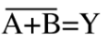
The NOR gate (OR then NOT)The output (x) will be high voltage if A and B input is low voltage. So X will be 1 if A and B are not 1. X = A NOR B or X = a + b or X =

The XOR/EOR gateThe output (x) will be high voltage if A or B input is high voltage. So X will be 1 or A or B are 1 but if A and B are 1, X will be 0. X = A XOR B or X = (a.b) + (a.b) or X =


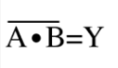
The NAND gate (AND then NOT)The output (x) will be low voltage if A and B input is high voltage. Output will be 1 unless A and B are 1. NAND gates are special because its a universal logic that makes NAND gates an alternative to making other gates. X = A NAND B or X = a.b or X =
NAND gates used to make other gates:
